


STM32-QFP64, Programmer Adapter
- Mã sản phẩm: STM32-QFP64
- Nhà sản xuất: Yamaichi
- Website hỗ trợ: https://www.proe.vn
2.200.000₫
- PACKAGE CONTENT
-
Weight: 0.09 kg
- STM32-QFP64 × 1
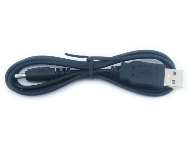
- USB power cable × 1
1

2

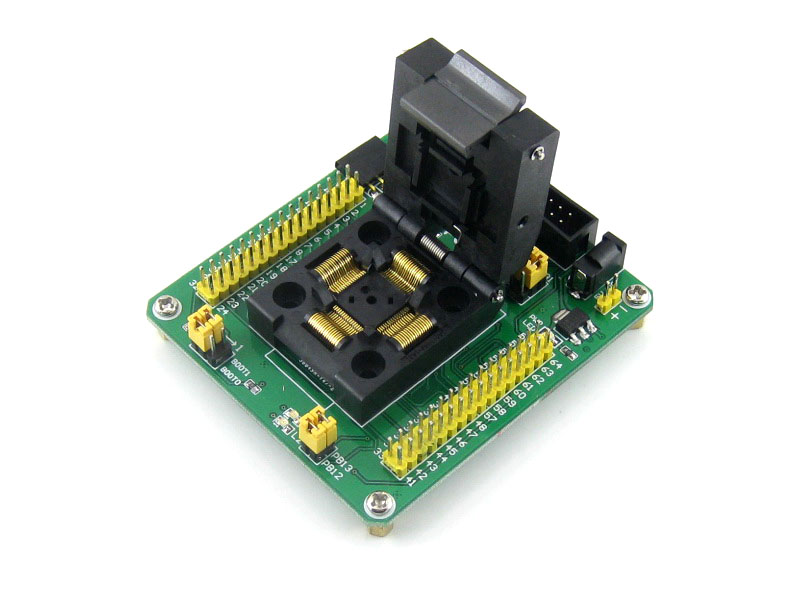
Yamaichi IC Test & Burn-In Socket With A Simple Board, Specifically Designed For STM32 Microcontroller In QFP64(0.5mm Pitch) Package
Features
- 20-pin JTAG/SWD port and/or 4-pin USART1 interface for programming/testing
- External crystal can be connected via on board socket for system clock
- Onboard 32.768K crystal oscillator
- Two LED indicators for testing, which are connected to the I/O pins via jumpers
- All the MCU pins are accessible on expansion connectors
- pin header pitch: 2.54mm(100mil)
Supported Devices
STM32 microcontroller in QFP64(0.5mm pitch) package with compatible pinouts:
- STM32L1xxR series (STM32L151R8, STM32L152RB, etc.)
- STM32F0xxR series (STM32F051RC, STM32F051RB, etc.)
- STM32F1xxR series (STM32F103RC, STM32F100RB, etc.)
- STM32F2xxR series (STM32F207RC, STM32F215RB, etc.)
- STM32F3xxR series (STM32F303R8, STM32F373RB, etc.)
- STM32F4xxR series (STM32F407RC, STM32F415RB, etc.)
Config the onboard "Device selection jumpers" according to the device to be programmed.
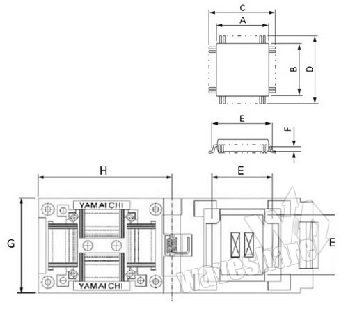
Outline and Dimensions
Unit: mm
| Part Number | Pitch | Pins | Applicable IC Dimensions (REF.) | Outside Dimensions (REF.) | |||
|---|---|---|---|---|---|---|---|
| A x B | C x D | E | F | G x H | |||
| IC51-0644-807 | 0.5 | 64 | 10.0 x 10.0 | 12.0 x 12.0 | 11.3 | - | 32.0 x 35.0 |
 |
|||||||
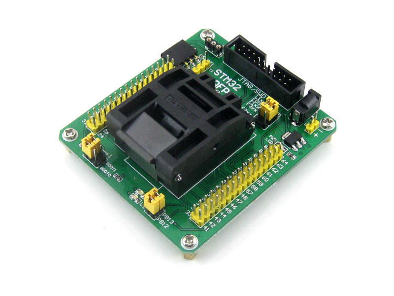
Photos
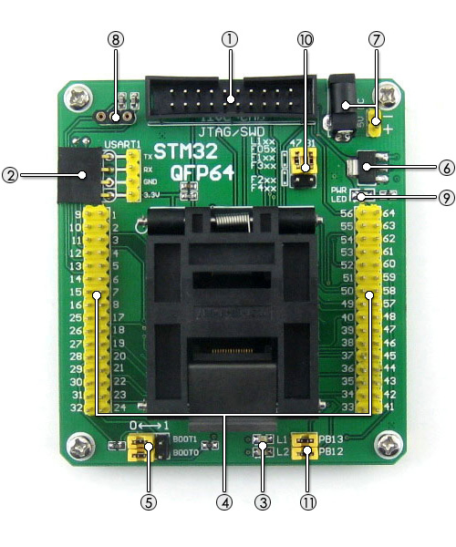
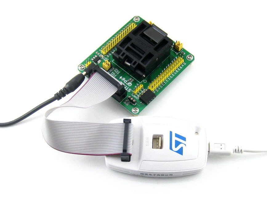
- JTAG/SWD port
- for programming/debugging/testing
- compatible with ST-LINK / J-LINK / ULINK2 / STX-RLINK
- USART1 port
- supports ISP and/or serial port debugging
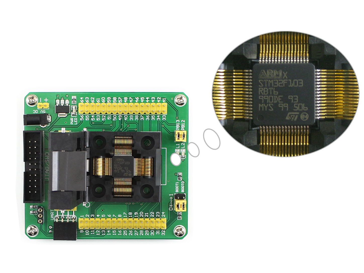
- LED indicators
- for quick testing
- Pin headers connected to MCU pins
- clearly labeled with onboard marks
- easy for testing and further expansion
- Boot mode configuration
- configuring the BOOT0 and BOOT1 via jumpers
- 3.3V onboard regulator
- AMS1117-3.3
- 5V power input
- DC jack or 2-pin header
- External crystal socket
- insert crystal to the holes on two sides, leave alone the middle hole
- Power indicator
- Device selection jumpers
- short the upper headers for STM32F1xx / STM32L1xx / STM32F05x / STM32F3xx
- short the lower headers for STM32F2xx / STM32F4xx
- LED jumpers
- short the jumpers to connect LEDs to MCU I/O pins for testing
- open the jumpers to disconnect
- 32.768K crystal (on bottom side)
- for internal RTC with calibration


JTAG/SWD Connector Layout
The STM32-QFP64 houses JTAG/SWD headers for connecting a programmer. The connector layout is shown in the figure 1 below.
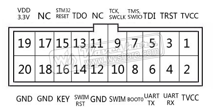
Figure 1. JTAG/SWD connector layout
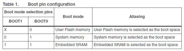
Boot Mode Configuration
Depending on the used pin configuration, the Flash memory, system memory or SRAM is selected as the boot space, as shown in Table 1 below.
Downloads
Development resources:schematic, etc.
Wiki: www.waveshare.com/wiki/STM32-QFP64
Điện tử ProE cung cấp linh kiện điện tử, thiết bị điện tử , linh kiện IoT chính hãng. ProE cung cấp dịch vụ đặt hàng linh kiện điện tử, thiết bị điện tử chính hãng theo yêu cầu cụ thể của khách hàng. Liên hệ : contact@proe.vn, SĐT: 0938946849
Website: www.proe.vn
Diễn đàn: https://www.facebook.com/groups/278263459284765/
Youtube Chanel: ProE Youtube
Facebook: ProE Facebook
Sản phẩm cùng loại
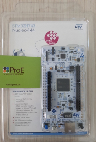
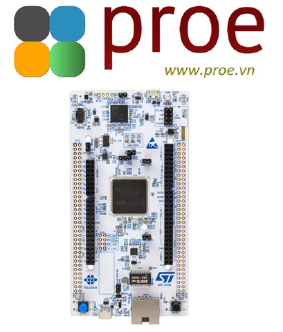
NUCLEO-H743ZI2
1.400.000₫
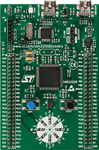
STM32F3 DISCOVERY
600.000₫
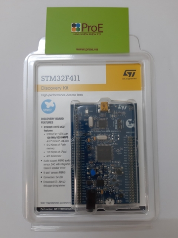
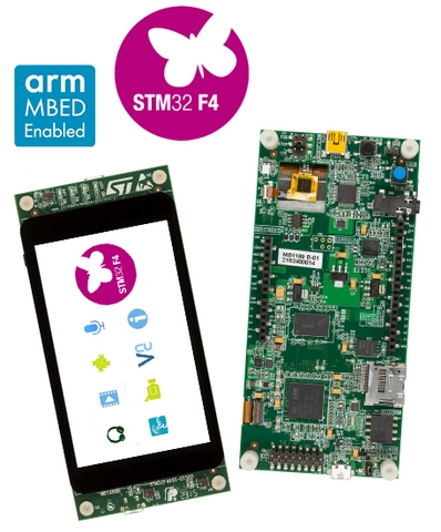
STM32F411 DISCOVERY
780.000₫

STM32F407G-DISC1
900.000₫
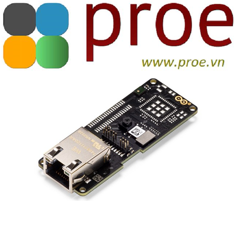
ASX00021 ARDUINO PORTENTA VISION SHIELD
1.950.000₫

NUCLEO-H723ZG
1.400.000₫
